
Skip to content
SVEN24/7 EMERGENCY SUPPORTContact24/7 EMERGENCY SUPPORT
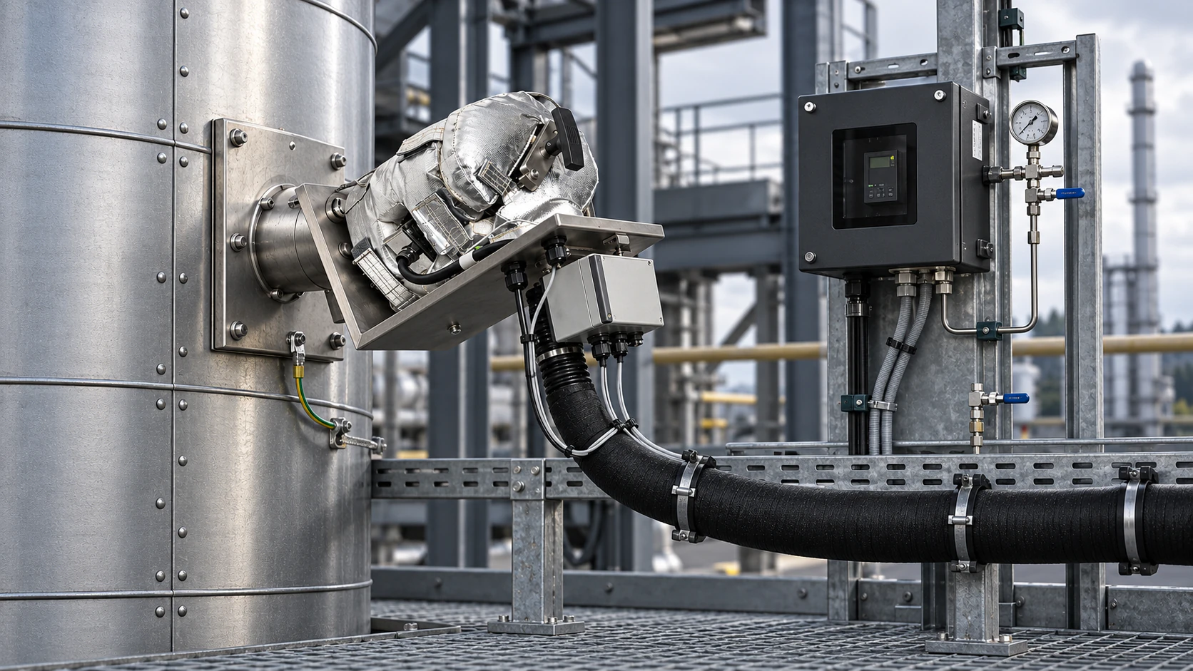
Installed measurement point with sampling equipment and sample line on an industrial duct
MEASUREMENT TECHNOLOGY · ARKTEC 7-STAGE

The measured value starts in the process.

From measurement point and sample extraction to sample line, sample conditioning, analyser and data handling, every stage can affect the value that is finally reported.

That is why ARKTEC troubleshoots, services and inspects the measuring system as a connected chain. The chain below describes an extractive system. For in-situ, dust and flow monitoring the stages look different, but the principle is the same.

01 PROCESS / MEASUREMENT POINT02 SAMPLE EXTRACTION / SAMPLING03 SAMPLE LINE04 SAMPLE CONDITIONING05 ANALYSER06 SIGNAL & DATA07 REPORTED RESULT
ARKTEC 7-STAGE · SELECT A STAGE
  1. WHAT CAN GO WRONGThe position of the measurement point, flow profile, dust and moisture affect whether the sample is representative.
    WHAT WE DOWe start from the existing measurement point and take process conditions into account when troubleshooting.
  2. WHAT CAN GO WRONGClogged filters, low probe temperature and damaged gaskets that let in air and dilute the sample gas.
    WHAT WE DOChecks of probe, filter, heating and leak-tightness. Replacement of filters and gaskets.
  3. WHAT CAN GO WRONGCold spots, broken heated zones, leaks at joints and condensation collecting at low points.
    WHAT WE DOChecks of temperature and leak-tightness along the line. Repair or replacement of defective parts.
  4. WHAT CAN GO WRONGCoolers that do not hold temperature, condensate that is not drained, worn pumps and reduced flow.
    WHAT WE DOService of coolers, pumps, filters and condensate drains. Checks of flow and response time.
  5. WHAT CAN GO WRONGZero or span drift, slow response, cross-sensitivities and component faults.
    WHAT WE DOTroubleshooting and repair, zero and span checks, and adjustment with calibration gas.
  6. WHAT CAN GO WRONGIncorrect scaling, mapping or time synchronisation between the analyser and the receiving system.
    WHAT WE DOComparison of the analyser's output signal with the recorded value.
  7. WHAT CAN GO WRONGA stable value can still be wrong if an earlier stage affects the sample.
    WHAT WE DOWe do not perform the calculations in the reporting system, but we link the result to the installation's technical history.
01 · PROCESS / MEASUREMENT POINT
WHAT CAN GO WRONGThe position of the measurement point, flow profile, dust and moisture affect whether the sample is representative.
WHAT WE DOWe start from the existing measurement point and take process conditions into account when troubleshooting.

Process / measurement point

PROCESS CONDITIONS · REPRESENTATIVENESS

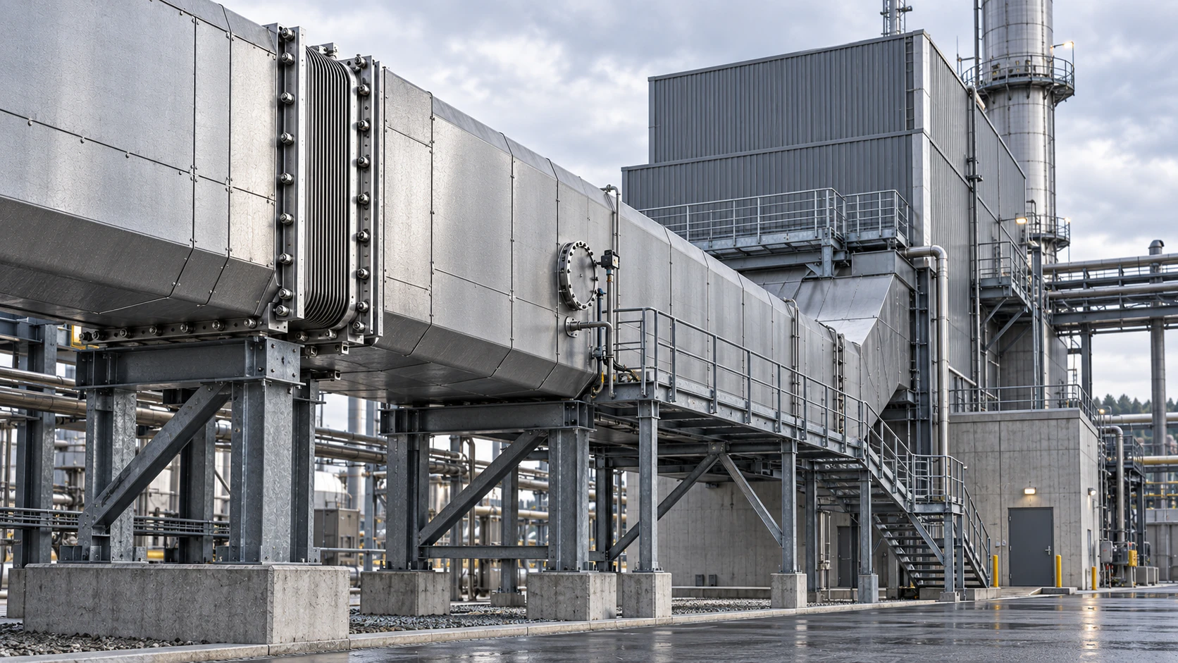
Temperature, moisture, dust, pressure and the flow profile in the duct affect the conditions for sampling. The position of the measurement point relative to the process geometry and its variation affects whether the sample is representative. ARKTEC starts from the existing measurement point and takes its conditions into account when assessing the rest of the measuring chain.
POSITIONFLOW PROFILETEMPERATUREMOISTUREDUST
Insulated process duct with flanges, support structure and service platform
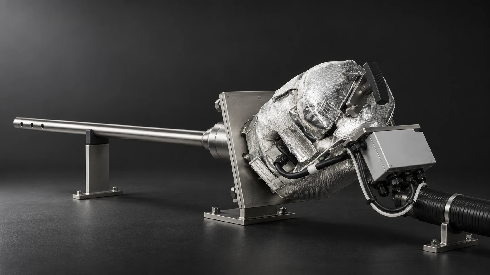
Heated sampling probe with insulated sample tubing and mounting flange

Sample extraction / sampling

PROBE · FILTER · HEATING · LEAK-TIGHTNESS

This is where the sample gas is extracted from the process. Probe, filter, heating, gaskets, leak-tightness and sample gas flow affect which sample is actually passed on through the system.

Leaks or damaged gaskets can let in ambient air — air ingress — which dilutes the sample gas and changes the measured concentrations. Filter loading or insufficient temperature can at the same time affect the flow and the composition of the sample.

LEAK-TIGHTNESSFILTER CONDITIONPROBE TEMPERATURESAMPLE GAS FLOW

Sample line

TRANSPORT · TEMPERATURE · LEAK-TIGHTNESS

The sample gas should reach the next stage with as little unintended change as possible. Temperature drops, leaks at joints, transport time and condensation can affect the sample before it reaches the sample conditioning or the analyser.

In heated systems, the correct temperature and unbroken heated zones are essential to avoid cold spots and unwanted condensation. Low points where condensate can collect also need attention.

HEATED ZONESCOLD SPOTSLEAK-TIGHTNESSRISK OF CONDENSATION
Heated sample line routed along an industrial walkway with brackets and cable tray

Sample conditioning

COOLING · FILTRATION · CONDENSATE · PUMP · FLOW

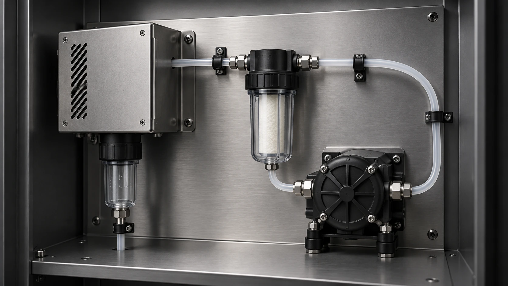
Sample conditioning adapts the sample gas to the requirements of the analyser and its measuring principle. Depending on the system, this can involve filtration, cooling, drying, condensate removal and control of the sample gas flow.

Coolers, filters, pumps, condensate drains and flow control affect both the condition of the sample and the response time of the system. Where relevant, the leak-tightness of the system is included too.
COOLERCONDENSATEFILTERPUMPFLOW
Sample conditioning system with cooler, filter, pump and tubing connections on a mounting plate

Analyser

MEASURING PRINCIPLE · ZERO · SPAN · RESPONSE

The analyser measures the sample gas that reaches the instrument. Measuring principle, instrument response, sample gas flow, cross-sensitivities and drift over time can affect the displayed value.

Zero and span checks, reference gas and instrument status are used to monitor the analyser’s performance. How much of the chain the check covers depends on where the reference gas is injected: at the analyser it says little about the sample gas path, at the probe more — but nothing about how representative the sample is.

What looks like drift or instability in the analyser can sometimes have its cause earlier in the chain, for example in flow, leaks, filter loading or sample conditioning.
ZEROSPANREFERENCE GASRESPONSEOPERATING STATUS
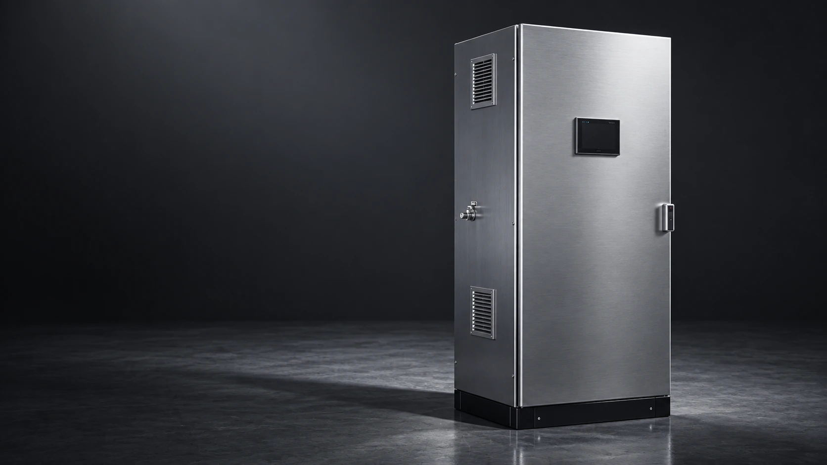
Analyser cabinet for industrial gas analysis with display and ventilation grilles
The analyser measures the gas it receives.

So the analyser can be working correctly while a fault exists earlier in the measuring chain.

Signal & data

SIGNAL TRANSMISSION · SCALING · STATUS · TIME

The value the analyser sends should match the value the receiving system reads. ARKTEC can check this, for example by comparing a known output signal with the recorded value. Scaling, analogue or digital transmission, units and status information affect how the signal becomes stored measurement data.

A correct instrument value can become wrong in the next system if the signal is scaled, mapped or handled incorrectly.
Scaling4–20 mA · MODBUS
Status informationSTATUS
TimestampingTIME SYNCHRONISATION
IntegrationPLC · DAHS
EXAMPLE INTERFACES · VARY BETWEEN INSTALLATIONS
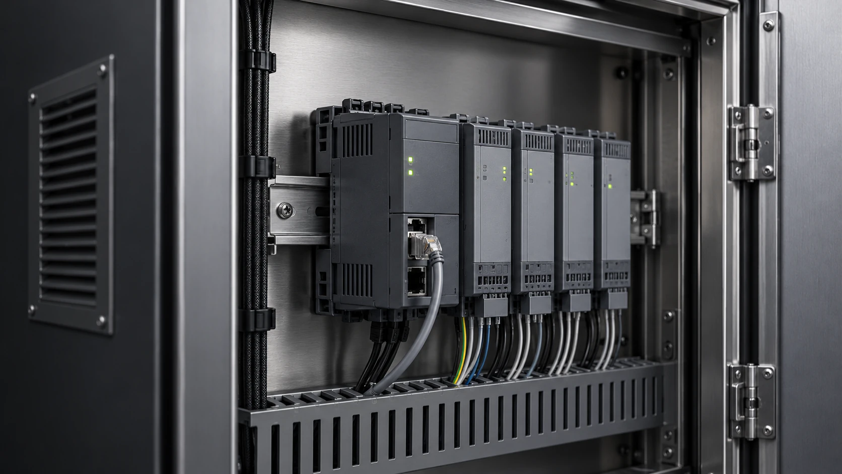
PLC and I/O modules on a DIN rail in a control cabinet with connected signal cables

Reported result

RESULT · STATUS · TECHNICAL HISTORY

The reported result is the end product of the measuring chain. Calculations, conversions to reference conditions and reporting are done in the site’s emissions reporting system, which is often supplied and maintained by an external vendor.

ARKTEC does not perform these calculations. We track the result: relevant results and status — for example whether an external test passed or showed a deviation — are entered in the installation’s technical history and used as context at future inspections.

The reported result is therefore the result of the entire chain — not just the analyser’s measurement.
EXAMPLE VIEW · NOT REAL SITE DATADOCUMENTED · EXAMPLE
EXTERNAL TESTPassed
IN TECHNICAL HISTORYLinked to C11
RESULTSTATUSDEVIATION / PASSEDLINK TO HISTORY
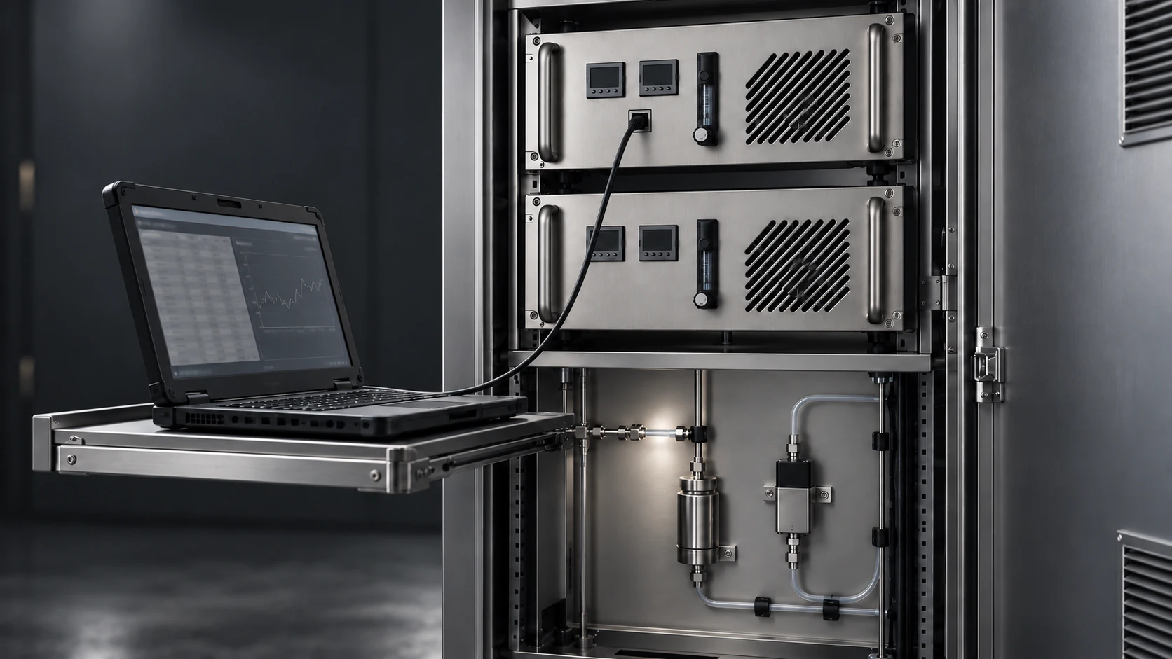
Laptop connected to a data port on an analyser cabinet for retrieving measurement data

A stable value is not automatically a correct value.

An error can be stable over time. That is why the measured value needs to be assessed together with the technical condition of the rest of the measuring chain.

MEASUREMENT ASSURANCE & DOCUMENTATION →SEE OUR SERVICES

Tell us about your measuring system.

Briefly describe the installation and what you need help with, such as a fault, a repair, maintenance, a spare part or a service agreement. Include the manufacturer and model if you can, so we can prepare for the first conversation.

Based in Stockholm, working throughout Sweden.

ARKTEC
ARKTEC 7-STAGE · FROM PROCESS TO REPORTED RESULT